采用ROHM原装BH1750FVI芯片供电电源:3-5V,光照度范围:0-65535lx传感器内置16bitAD转换器,直接数字输出,省略复杂的计算,省略标定,不区分环境光源接近于视觉灵敏度的分光特性,可对广泛的亮度进行1勒克斯的高精度测定。标准NXPICC通信协议,模块内部包含通信电平转换,可以与5V单片机io直接连接。
一、模块来源
二、规格参数
工作电压:3-5V
工作电流:200uA
探测范围:1~65536 lx
模块尺寸:32.6mm×15.2mm×11.6mm
输出方式: IIC
管脚数量:5 Pin
以上信息见厂家资料文件
三、移植过程
我们的目标是将例程移植至开发板上【能够测量光照强度】。首先要获取资料,查看数据手册应如何实现读取数据,再移植至我们的工程。
1、查看资料
测量步骤:
- 模块上电后,进入掉电模式,需要通过IIC发送Power On命令启动。
- 模块启动之后通过IIC发送测量命令进行测量。
- 测量命令分有单次测量和连续测量,测量完毕之后又进入掉电模式。
各个命令的对应的值见下表。
我们使用到的有:
Power On(0x01):启动模块,让其等待测量命令。
Continuously H-Resolution Mode(0X10):以1LX分辨率开始测量。测量时间一般为120ms(手册推荐使用该命令)
One Time H-Resolution Mode(0X20):以1lx分辨率开始测量,测量时间通常为120ms。操作完成后,系统自动设置为”掉电”模式。
发送时序:
起始信号 -> 发送器件地址+写 -> 等待模块应答 -> 发送命令 -> 等待模块应答 -> 停止信号。
读取时序:
起始信号 -> 发送器件地址+读 -> 等待模块应答 -> 接收数据高8位 -> 主机发送应答 -> 接收数据低8位 -> 主机发送非应答 -> 停止信号。
读取完成之后,将数据高低位整合再除以1.2即可得到光照强度数据。
2、引脚选择
| VCC | 3V3 |
| GND | GND |
| SCL | P408 |
| SDA | P409 |
3、图形化配置
- 打开图形化界面:
- 设置
Pin:
Ctrl + S保存!- 点击右上角
Generate Project Content生成代码。
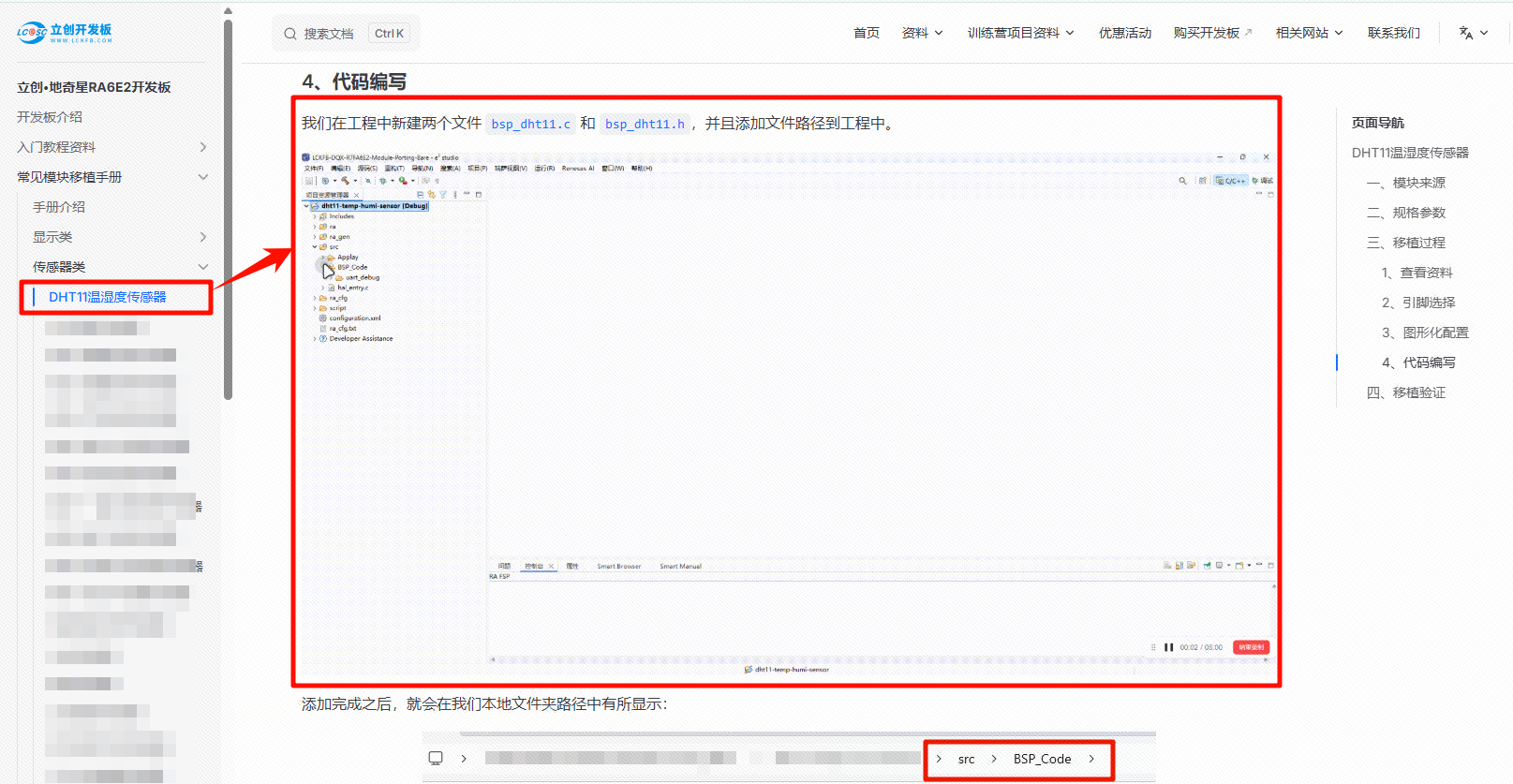
4、代码编写
新建两个文件 bsp_bh1750.c 和 bsp_bh1750.h,并且将头文件路径添加到编译器中。
在文件 bsp_bh1750.c 和 bsp_bh1750.h 中,编写如下代码。
/*
 * 立创开发板软硬件资料与相关扩展板软硬件资料官网全部开源
 * 开发板官网:www.lckfb.com
 * 文档网站:wiki.lckfb.com
 * 技术支持常驻论坛,任何技术问题欢迎随时交流学习
 * 嘉立创社区问答:https://www.jlc-bbs.com/lckfb
 * 关注bilibili账号:【立创开发板】,掌握我们的最新动态!
 * 不靠卖板赚钱,以培养中国工程师为己任
 */

#ifndef BSP_CODE_BSP_BH1750_H_
#define BSP_CODE_BSP_BH1750_H_

#include "hal_data.h"
#include <stdio.h>

#ifndef u8
#define u8 uint8_t
#endif
#ifndef u16
#define u16 uint16_t
#endif
#ifndef u32
#define u32 uint32_t
#endif

#ifndef delay_ms
#define delay_ms(x)   R_BSP_SoftwareDelay(x, BSP_DELAY_UNITS_MILLISECONDS)
#endif
#ifndef delay_1ms
#define delay_1ms(x)  R_BSP_SoftwareDelay(x, BSP_DELAY_UNITS_MILLISECONDS)
#endif
#ifndef delay_us
#define delay_us(x)   R_BSP_SoftwareDelay(x, BSP_DELAY_UNITS_MICROSECONDS)
#endif
#ifndef delay_1us
#define delay_1us(x)  R_BSP_SoftwareDelay(x, BSP_DELAY_UNITS_MICROSECONDS)
#endif


#define Module_SCL_PIN   BSP_IO_PORT_04_PIN_08 // SCL
#define Module_SDA_PIN   BSP_IO_PORT_04_PIN_09 // SDA

//SDA输入模式
#define SDA_IN() { \
    fsp_err_t err = R_IOPORT_PinCfg(&g_ioport_ctrl, Module_SDA_PIN, \
                    (uint32_t) IOPORT_CFG_PORT_DIRECTION_INPUT); \
    if(err != FSP_SUCCESS) { \
        printf("GPIO Mode Set INPUT Failed!!\r\n"); \
    } \
}

//SDA输出模式
#define SDA_OUT() { \
    fsp_err_t err = R_IOPORT_PinCfg(&g_ioport_ctrl, Module_SDA_PIN, \
            ((uint32_t) IOPORT_CFG_DRIVE_HIGH \
		| (uint32_t) IOPORT_CFG_NMOS_ENABLE \
		| (uint32_t) IOPORT_CFG_PORT_DIRECTION_OUTPUT \
		| (uint32_t) IOPORT_CFG_PORT_OUTPUT_HIGH)); \
    if(err != FSP_SUCCESS) { \
        printf("GPIO Mode Set OUTPUT Failed!!\r\n"); \
    } \
}

// SCL引脚和SDA引脚的输出
#define SCL(BIT)    R_IOPORT_PinWrite(&g_ioport_ctrl, Module_SCL_PIN, BIT)
#define SDA(BIT)    R_IOPORT_PinWrite(&g_ioport_ctrl, Module_SDA_PIN, BIT)

// 获取SDA引脚的电平状态
static inline bsp_io_level_t SDA_GET(void) {
    bsp_io_level_t p_pin_value;
    fsp_err_t err = R_IOPORT_PinRead(&g_ioport_ctrl, Module_SDA_PIN, &p_pin_value);
    if(err != FSP_SUCCESS) {
        printf("GPIO Input Read Failed!!\r\n");
    }
    return p_pin_value;
}

char Multiple_read_BH1750(float *bh1750_value);
char Single_Write_BH1750(uint8_t REG_Address);
void BH1750_Init(void);

#endif /* BSP_CODE_BSP_BH1750_H_ *//*
* 立创开发板软硬件资料与相关扩展板软硬件资料官网全部开源
* 开发板官网:www.lckfb.com
* 文档网站:wiki.lckfb.com
* 技术支持常驻论坛,任何技术问题欢迎随时交流学习
* 嘉立创社区问答:https://www.jlc-bbs.com/lckfb
* 关注bilibili账号:【立创开发板】,掌握我们的最新动态!
* 不靠卖板赚钱,以培养中国工程师为己任
*/
#include "bsp_bh1750.h"
#include "stdio.h"
// 定义器件在IIC总线中的从地址,根据ALT ADDRESS地址引脚不同修改
// ALT ADDRESS引脚接地时地址为0x46,接电源时地址为0xB8
#define SlaveAddress 0x46
/******************************************************************
* 函 数 名 称:IIC_Start
* 函 数 说 明:IIC起始时序
* 函 数 形 参:无
* 函 数 返 回:无
* 作 者:LCKFB
* 备 注:无
******************************************************************/
void IIC_Start(void)
{
SDA_OUT();
SDA(1);
delay_us(5);
SCL(1);
delay_us(5);
SDA(0);
delay_us(5);
SCL(0);
delay_us(5);
}
/******************************************************************
* 函 数 名 称:IIC_Stop
* 函 数 说 明:IIC停止信号
* 函 数 形 参:无
* 函 数 返 回:无
* 作 者:LCKFB
* 备 注:无
******************************************************************/
void IIC_Stop(void)
{
SDA_OUT();
SCL(0);
SDA(0);
SCL(1);
delay_us(5);
SDA(1);
delay_us(5);
}
/******************************************************************
* 函 数 名 称:IIC_Send_Ack
* 函 数 说 明:主机发送应答或者非应答信号
* 函 数 形 参:0发送应答 1发送非应答
* 函 数 返 回:无
* 作 者:LCKFB
* 备 注:无
******************************************************************/
void IIC_Send_Ack(unsigned char ack)
{
SDA_OUT();
SCL(0);
SDA(0);
delay_us(5);
if(!ack) SDA(0);
else SDA(1);
SCL(1);
delay_us(5);
SCL(0);
SDA(1);
}
/******************************************************************
* 函 数 名 称:I2C_WaitAck
* 函 数 说 明:等待从机应答
* 函 数 形 参:无
* 函 数 返 回:0有应答 1超时无应答
* 作 者:LCKFB
* 备 注:无
******************************************************************/
unsigned char I2C_WaitAck(void)
{
char ack = 0;
unsigned char ack_flag = 10;
SCL(0);
SDA(1);
SDA_IN();
delay_us(5);
SCL(1);
delay_us(5);
while( (SDA_GET()==1) && ( ack_flag ) )
{
ack_flag--;
delay_us(5);
}
if( ack_flag <= 0 )
{
IIC_Stop();
return 1;
}
else
{
SCL(0);
SDA_OUT();
}
return ack;
}
/******************************************************************
* 函 数 名 称:Send_Byte
* 函 数 说 明:写入一个字节
* 函 数 形 参:dat要写人的数据
* 函 数 返 回:无
* 作 者:LCKFB
* 备 注:无
******************************************************************/
void Send_Byte(uint8_t dat)
{
int i = 0;
SDA_OUT();
SCL(0);//拉低时钟开始数据传输
for( i = 0; i < 8; i++ )
{
SDA( dat & 0x80 );
delay_us(1);
SCL(1);
delay_us(5);
SCL(0);
delay_us(5);
dat<<=1;
}
}
/******************************************************************
* 函 数 名 称:Read_Byte
* 函 数 说 明:IIC读时序
* 函 数 形 参:无
* 函 数 返 回:读到的数据
* 作 者:LCKFB
* 备 注:无
******************************************************************/
unsigned char Read_Byte(void)
{
unsigned char i,receive=0;
SDA_IN();//SDA设置为输入
for(i=0;i<8;i++ )
{
SCL(0);
delay_us(5);
SCL(1);
delay_us(5);
receive<<=1;
if( SDA_GET() )
{
receive|=1;
}
delay_us(5);
}
SCL(0);
return receive;
}
/******************************************************************
* 函 数 名 称:Single_Write
* 函 数 说 明:向BH1750写入命令
* 函 数 形 参:REG_Address=写入的命令
* 函 数 返 回:0写入成功 1=器件地址错误(识别不到模块) 2=命令错误
* 作 者:LCKFB
* 备 注:无
******************************************************************/
char Single_Write_BH1750(uint8_t REG_Address)
{
IIC_Start(); //起始信号
Send_Byte(SlaveAddress); //发送设备地址+写信号
if( I2C_WaitAck() != 0 )return 1;
Send_Byte(REG_Address); //内部寄存器地址
if( I2C_WaitAck() != 0 )return 2;
IIC_Stop(); //发送停止信号
return 0;
}
/******************************************************************
* 函 数 名 称:Multiple_read_BH1750
* 函 数 说 明:读取BH1750内部数据
* 函 数 形 参:bh1750_value: 光照度(单位:lx)
* 函 数 返 回:0成功
* 作 者:LCKFB
* 备 注:无
******************************************************************/
char Multiple_read_BH1750(float *bh1750_value)
{
uint16_t dis_data=0;
uint8_t dat_buff[2];
Single_Write_BH1750(0x10); // 连续高分辨率模式测量
delay_ms(180); // 测量一般需要120ms
IIC_Start(); //起始信号
Send_Byte(SlaveAddress+1); //发送设备地址+读信号
I2C_WaitAck();
dat_buff[0] = Read_Byte(); //读取高8位
IIC_Send_Ack(0); //回应ACK
dat_buff[1] = Read_Byte(); //读取低8位
IIC_Send_Ack(1); //回应NOACK
IIC_Stop(); //停止信号
//合成数据,即光照数据
dis_data=( (uint16_t)dat_buff[0] << 8 ) + dat_buff[1];
*bh1750_value = (float)dis_data/1.2f;
return 0;
}
/******************************************************************
* 函 数 名 称:BH1750_Init
* 函 数 说 明:初始化BH1750
* 函 数 形 参:无
* 函 数 返 回:无
* 作 者:LCKFB
* 备 注:无
******************************************************************/
void BH1750_Init(void)
{
SCL(1);
SDA(1);
delay_ms(100); // 等待传感器稳定
Single_Write_BH1750(0x01);//上电
delay_ms(100); // 等待传感器稳定
}四、移植验证
在 src\Applay\app.c 中输入代码如下:
/*
 * 立创开发板软硬件资料与相关扩展板软硬件资料官网全部开源
 * 开发板官网:www.lckfb.com
 * 文档网站:wiki.lckfb.com
 * 技术支持常驻论坛,任何技术问题欢迎随时交流学习
 * 嘉立创社区问答:https://www.jlc-bbs.com/lckfb
 * 关注bilibili账号:【立创开发板】,掌握我们的最新动态!
 * 不靠卖板赚钱,以培养中国工程师为己任
 */

#include "app.h"
#include "stdio.h"

#include "bsp_uart.h"
#include "bsp_bh1750.h"
/******************************************************************
 * 函 数 名 称:led_blink
 * 函 数 说 明:该函数用于控制LED灯的闪烁效果
 *             运行时,LED灯每隔500毫秒闪烁一次
 *             完整运行此函数需要1s时间
 * 函 数 形 参:无
 * 函 数 返 回:无
 * 作       者:LC
 * 备       注:无
******************************************************************/
static void led_blink(void)
{
    /* Set the pin to low */
    R_IOPORT_PinWrite(&g_ioport_ctrl, BSP_IO_PORT_04_PIN_02, BSP_IO_LEVEL_LOW);

    /* Delay for 500 milliseconds */
    R_BSP_SoftwareDelay(500, BSP_DELAY_UNITS_MILLISECONDS);

    /* Set the pin to high */
    R_IOPORT_PinWrite(&g_ioport_ctrl, BSP_IO_PORT_04_PIN_02, BSP_IO_LEVEL_HIGH);

    /* Delay for another 500 milliseconds */
    R_BSP_SoftwareDelay(500, BSP_DELAY_UNITS_MILLISECONDS);
}


/******************************************************************
 * 函 数 名 称:Run
 * 函 数 说 明:该函数是用户自定义的入口函数,等效于 main_app() 函数。
 *             在此函数中可以编写用户的应用逻辑代码。
 * 函 数 形 参:无
 * 函 数 返 回:无
 * 作       者:LC
 * 备       注:无
******************************************************************/
void Run(void)
{
    /* 初始化调试串口 */
    /* | RX:P100 | TX:P101 | */
    UART0_Debug_Init();

    printf("\r\n= = = = = = = = = = = = = = = = = = = = = = = = = = = = = = = =\r\n");
    printf("\r\n=== Welcome to use the DQX-R7FA6E2BB3CNE development board ====\r\n");
    printf("\r\n======================= www.lckfb.com =========================\r\n");
    printf("\r\n======================= wiki.lckfb.com ========================\r\n");
    printf("\r\n======================= [Debug Uart0] =========================\r\n");
    printf("\r\n=================== | RX:P100 | TX:P101 | =====================\r\n");
    printf("\r\n= = = = = = = = = = = = = = = = = = = = = = = = = = = = = = = =\r\n");

    /* BH1750 Sensor Init */
    BH1750_Init();
    printf("\r\nBH1750 Sensor Init Success!\r\n");

    while(1)
    {
        float lux = 0;
        if(Multiple_read_BH1750(&lux) == 0) {
            printf("\r\nBH1750 Lux: %.2f lx\r\n", lux);
        } else {
            printf("\r\nBH1750 Read Error\r\n");
        }
        delay_1ms(500); // Delay for 500ms before next reading
    }
}编译烧录。
【代码下载】
- 跳转去下载模块移植代码:【点击跳转🚀】